Introduction
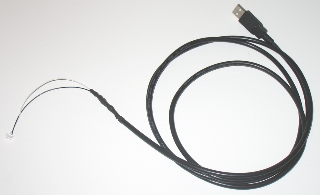
Building a USB ICS adapter for Kyosho Mini-Z and dNaNo cars is easy if you have some basic soldering skills. The ICS adapters used by these cars are basically a low voltage serial port that uses 1 wire to transmit and receive data.
This hardware will work with the Flip Side Racing ICS cross platform software along with other Mini-Z ICS programs.
Design Overview
To keep the design simple we will use an already existing USB to Serial TTL adapter and use a diode to bridge the transmit and receive lines to 1 wire. USB Serial to TTL adapters will get the voltage level close to where we need it for the Kyosho PCB's. Since the dNaNo operates at 3.7 volts it is safest if we get our TTL voltage down to that level or below.
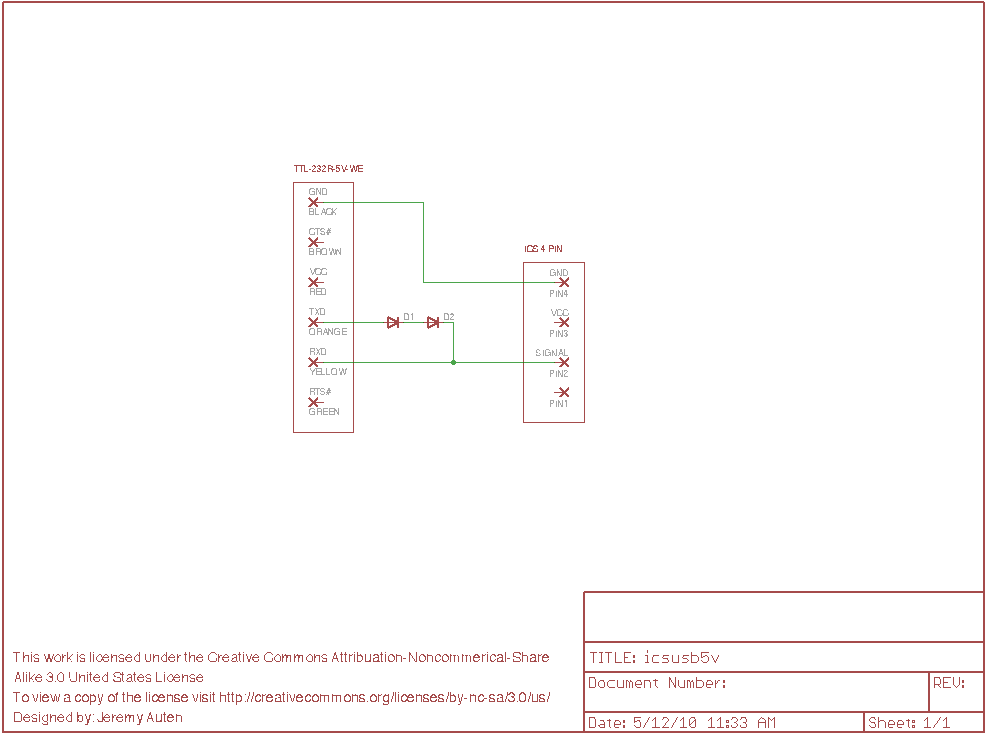
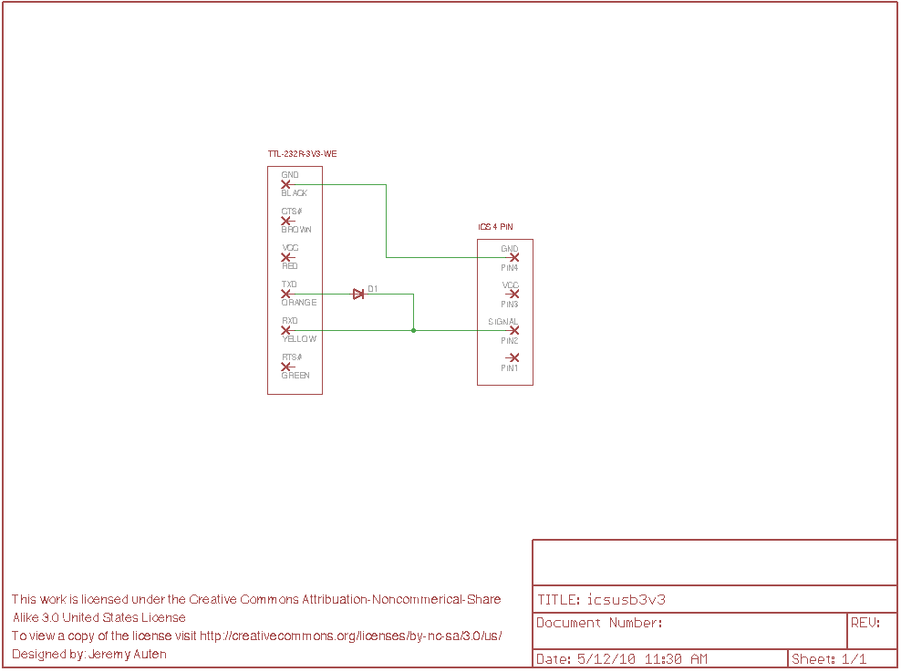
Using transistors to bridge the transmit and receive lines together would be a better design since by using a diode we will get an echo of all the transmitted data back to the computer. The Flip Side ICS Software will ignore this echoed data so it is not a concern. The diode will also drop the voltage level by approximately .7 volts. This allows us to start with a 5 volt USB to TTL adapter and use 2 diodes to get the voltage to 3.6 volts, right around the same voltage as the dNaNo. It may be possible that a 3.3 volt TTL adapter can also be used but use only 1 diode in that case. The Mini-Z and dNaNo boards will communicate at lower voltages but going over there voltage limits could create problems.
Overall this design allows us to build a USB to ICS adapter with a minimal amount of parts.
Donations
If you found this information useful please consider donating to help support our efforts.
Schematics
5 volt USB to TTL adapter
Below is a schematic based on a 5 volt USB to TTL adapter. I have successfully built this design. Notice the use of 2 diodes, this brings the voltage level down to approximately 3.6 volts. Click on the image to see a larger version.
3.3 volt USB to TTL adapter, UNVERIFIED DESIGN
Below is a schematic based on a 3.3 volt USB to TTL adapter. I have not attempted to use a 3.3 volt TTL device so I do not know if this will work. Notice the use of 1 diode, this brings the voltage level down to approximately 2.6 volts. While this should work you may need to use a germanium diode as it only has a .1 volt drop. Click on the image to see a larger version.
Parts
Connector Parts
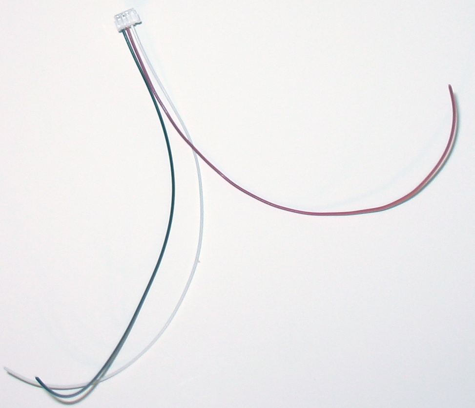
1.5MM JST ZH 26/28AWG crimp pins
26/28 gauge stranded wire
Diodes
Use 1 diode for a 3.3 volt TTL to USB adapter and 2 for a 5 volt TTL to USB adapter. Below are links to Digi-Key or SparkFun? for the same part.
1N4148 Small Signal Switching Diode from Digi-Key
1N4148 Small Signal Switching Diode from SparkFun
USB to TTL adapters
You will need to also choose one of the following USB to Serial TTL adapters.
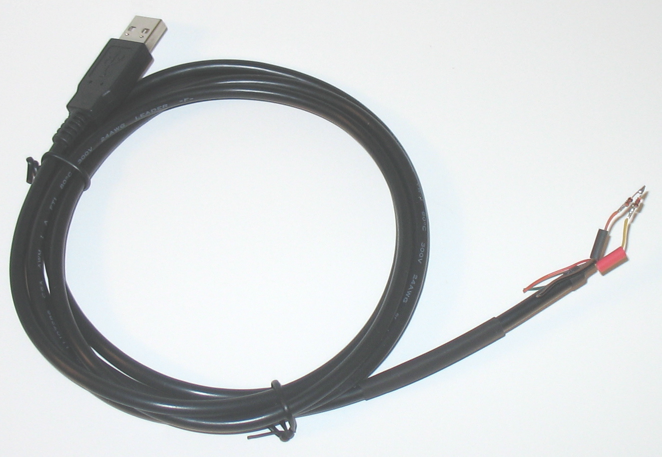
5V FTDI TTL to USB Convertor, wire end (I have successfully built this using 2 diodes with this one)
3.3V FTDI TTL to USB Convertor, wire end (UNVERIFIED DESIGN, use 1 diode with this one)
There are other versions of this adapter available with different types of connectors such as a 3 pin audio jack or a .1" pin connector. If you search for TTL-232R you will find the various versions of the FTDI adapter.
Construction
Detailed below is the construction of a ICS adapter using a USB to 5 volt serial TTL adapter. While using a 3.3 volt TTL adapter may work the 5 volt adapter is the only design I have verified to operate properly.
The hardest part of constructing this adapter is crimping the pins needed for the JST ZH cable. These pins are small and you will want a proper crimping tool to do this task.
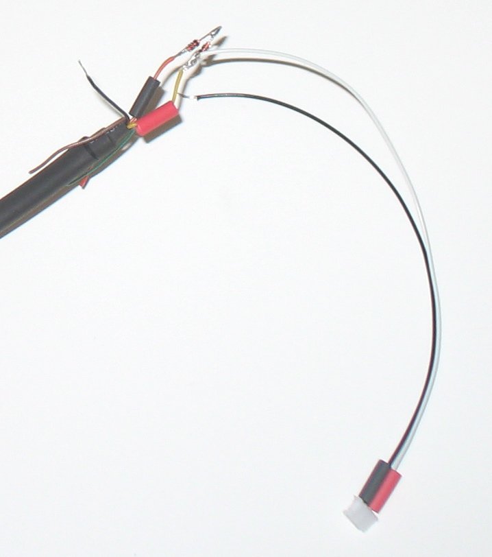
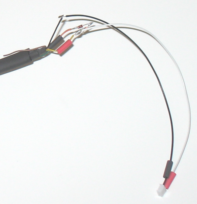
After you have built your connector there are 1 or 2 diodes that need soldered to bridge the transmit (orange) and receive (yellow) wires. When soldering the diodes in place make sure the black line is facing the yellow (receive) wire. If the diodes are installed backwards your adapter will not work.
Once the diodes are installed you must make an additional connection between the yellow (receive) wire and pin 2 of the JST ZH connector. This is the signal pin. Out of the 4 pins in the connector only the signal and ground pins must be connected.
Finally to connect the ground lines you must connect the black (ground) wire from the USB to TTL adapter to pin 4 of the JST ZH connector.
You should now have your own USB to ICS adapter, congratulations.
Pre-built Hardware
If you would rather buy an inexpensive USB cable built by us you can use the Buy Now button below to buy one for $35 plus shipping. This cable is built using the instructions detailed on this page.
License

This work is licensed under a Creative Commons Attribution-Noncommercial-Share Alike 3.0 United States License.

