Introduction
Building a Bluetooth ICS adapter for Kyosho Mini-Z and dNaNo cars is easy if you have some basic soldering skills and some moderate computer skills. The ICS adapters used by these cars are basically a low voltage serial port that uses 1 wire to transmit and receive data.
Warning
Do not try plug a cable directly into the Kyosho ICS port from a serial port on a computer. Computers serial ports operate at +/- 12 volts while the Kyosho Mini-Z's operate around 5 volts and dNaNo's operate around 3.7 volts. Without some sort of circuitry between a standard serial port and the ICS port to change the voltage level you will damage your Kyosho board.
Design Overview
To keep the design simple we will use an already existing Bluetooth to Serial TTL adapter and use a diode to bridge the transmit and receive lines to 1 wire.
Using transistors to bridge the transmit and receive lines together would be a better design since by using a diode we will get an echo of all the transmitted data back to the computer. The Flip Side ICS Software will ignore this echoed data so it is not a concern. The diode will also drop the voltage level by approximately .7 volts. If we start with a 3.3 volt Bluetooth to Serial TTL adapter and use 1 diode that drops the voltage to 2.6 volts for the transmitted data. The Mini-Z and dNaNo boards will communicate at this lower voltages but going over there voltage limits would create problems.
The chosen bluetooth module is the SparkFun? BlueSmirf? Gold module. This module is based on the RN-41 bluetooth module from Roving Networks but adds a voltage regulator and convertor to allow it to operate from between 3.3 and 6 volts. The module will be powered from the dNaNo or Mini-Z which is why we need the voltage regulator and the i/o for the module only operates at a maximum voltage of 3.3 volts which is why we need a convertor.
Overall this design allows us to build a Bluetooth ICS adapter with a minimal amount of parts.
Schematics
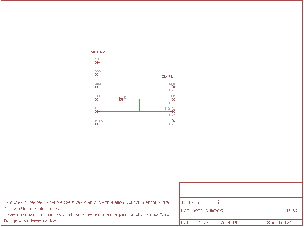
Below is a schematic based on the SparkFun? BlueSmirf? Gold adapter. Click on the image to see a larger version.
Parts
Connector Parts
1.5MM JST ZH 26/28AWG crimp pins
26/28 gauge stranded wire
Diode
1N4148 Small Signal Switching Diode
Bluetooth adapter
SparkFun BlueSmirf Gold adapter
Construction
The hardest part of constructing this adapter is crimping the pins needed for the JST ZH cable. These pins are small and you will want a proper crimping tool to do this task.
After you have built your connector there 1 diode that needs to be soldered to bridge the transmit (TX-O) and receive (RX-O) pins. When soldering the diode in place make sure the black line is facing the RX-O (receive) wire. If the diode is installed backwards your adapter will not work.
Once the diodes are installed you must make an additional connection between the RX-O (receive) wire and pin 2 of the JST ZH connector. This is the signal pin. Out of the 4 pins in the connector only the signal, vcc and ground pins must be connected.
Now you can connect the vcc line from the BlueSmirf? to the vcc line of the JST ZH connector, pin 3.
Finally to connect the ground lines you must connect the GND (ground) wire from the USB to TTL adapter to pin 4 of the JST ZH connector.
You should now have your own USB to ICS adapter, congratulations.
Configuring the adapter
You must first configure your operating system to recognize this new bluetooth device. How this is done depends on your bluetooth module in your computer and your operating system. The module itself has a default Passkey of 1234. After it is properly configured you will have a new serial port to use.
After you have the bluetooth module paired on your computer you need to configure the module to the correct speed. By default the BlueSmirf? module is set to 115200 baud but the Kyosho boards only communicate at 9600 baud. Before the adapter can be used it must be configured. To do this you must enter the module in command mode. This is done by send the command $$$ after the module is powered up using a terminal program such as screen in Linux and Mac OSX or HyperTerm? in Windows. This must be done within 60 seconds of powering the module on. After you have entered command mode you must send a set command to change the baud rate. Send the command SU,96 to set the module to 9600 baud. After you have sent these commands turn the adapter off and back on, it will now always start up at 9600 baud.
Bluetooth module information
You can find further information on this module in a couple of spots.
SparkFun BlueSmirf information
Roving Networks RN-41 bluetooth module information
License

This work is licensed under a Creative Commons Attribution-Noncommercial-Share Alike 3.0 United States License.

